About
This is a complex project that requires a redesign of the roadway layout to fix the current sidewalk issues. This is how the road layout design will will look. There are four different breakouts because each segment requires a different type of fix.
You can also view the zoomed-in layouts by scrolling past this infographic.
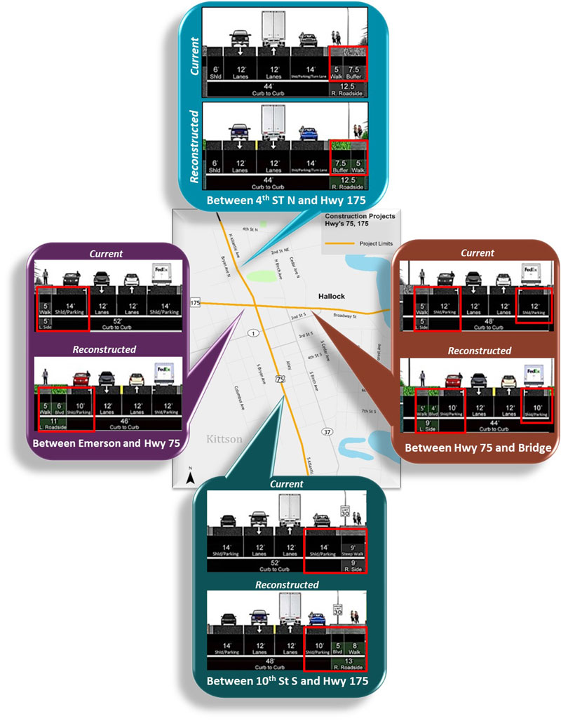
This infographic shows the layout differences for each highway section in Hallock
Hwy 75
Fourth Street North to Broadway Street (Hwy 175)
This layout only changes by switching the boulevard and the sidewalk along the northbound lane, there is no curb shift.
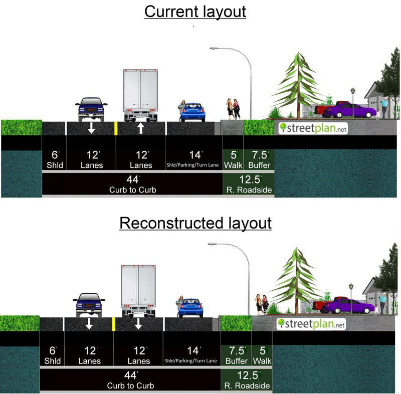
Fourth Street North to Broadway Street (Hwy 175) layout
Broadway Street (Hwy 175) to 10th Street South
This layout changes by replacing 4 feet of the paved shoulder on the northbound lane with concrete sidewalk.
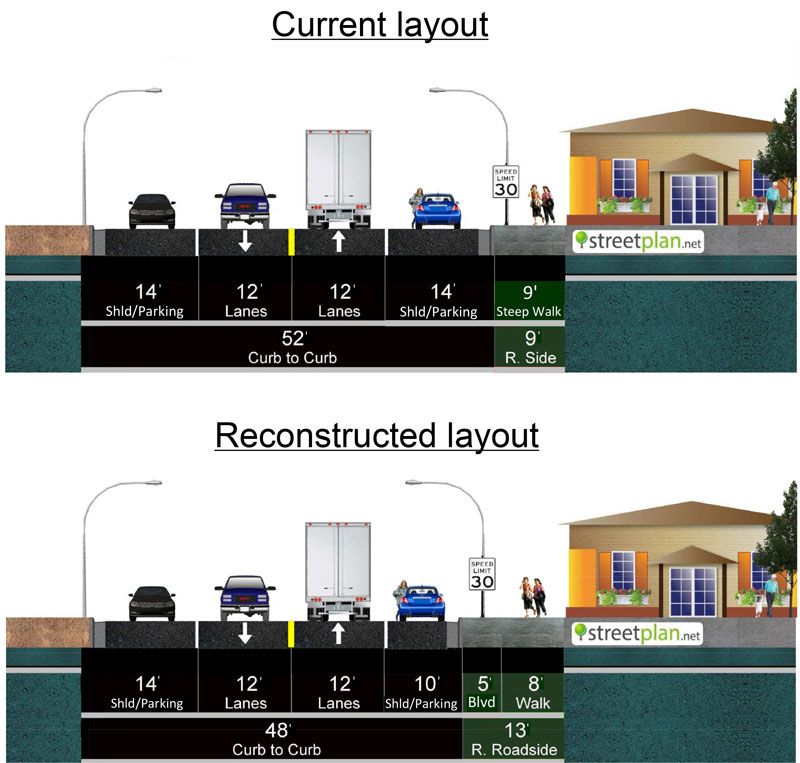
Broadway Street (Highway 175) to 10th St S layout
Hwy 175
Emerson Avenue to Atlantic Avenue (Hwy 75)
This layout changes by replacing a total of 6 feet of the paved shoulders with a new boulevard space on the westbound lane.
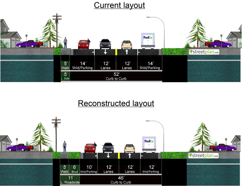
Emerson Avenue to Atlantic Avenue (Hwy 75) layout
Atlantic Avenue (Hwy 75) to Two Rivers Bridge
This layout changes by replacing a total of 4 feet of the paved shoulders with a new boulevard space on the eastbound lane.
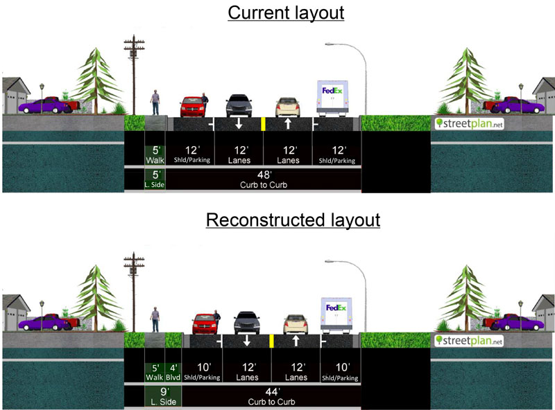
Atlantic Avenue (Hwy 75) to Two Rivers Bridge layout
Curb shift
Although there are a number of considerations when taking a curb shift into account, in this circumstance the amount of pavement space must be reduced and a curb shift must take place.
In order to accommodate the minimum requirements needed to reconstruct sidewalks that meet ADA standards, the sidewalk slope has to be extended into the current pavement layout. A curb shift is the only way to feasibly accommodate that.

A curb shift is required for this project. This cross section shows how the new slope (in blue) needs to be extended out towards the driving surface.

